About Mike

Mike Stephens has been in the IT field for over 25 years and with Microsoft for over 20. Currently he is a Senior Program Manager in the Azure Cloud Operating System and Intelligent Edge where his area of focus is Windows Hello for Business, client-side PKI, and cryptography. Additional security related areas where he collaborates include Modern Authentication, TLS, and FIPS validation. Prior to joining Enterprise Security, Mike was a Technical Writer for Group Policy and a Technical Lead within Microsoft Directory Services escalation support where he assisted Microsoft Premier customers with authentication, authorization, PKI, Group Policy and User Profile design and troubleshooting. He is a Microsoft Certified IT Professional (MCITP-EA) and a Microsoft Certified Trainer (MCT) Alumni. Mike has authored several TechNet articles and the Understand and Troubleshoot Dynamic Access Control in Windows Server 2012 whitepaper; is a contributing author to Introducing Windows Server 2012, Windows Server 2008 Active Directory Resource Kit, Windows 7 Resource Kit, Windows IT Pro Magazine, Ask Directory Services TechNet Blog, and the Group Policy TechNet Blog; and a Technical reviewer to Microsoft Windows™ Group Policy Guide and Group Policy, Profiles, and IntelliMirror for Windows 2003, Windows XP, and Windows 2000. Mike graduated Suma Cum Laude with a degree in Information Systems and a Graduate degree from Strayer University, and proud owner of four Siberian Huskies.

Azure Global Vnet Peering: Across the world in milliseconds

My new role on the Azure Fabric team had me playing with Azure Virtual Networks (commonly referred to as vNets).  More specifically, I was investigating vNet peering and global peering.

Virtual network peering enables you to seamlessly connect two Azure virtual networks. Once peered, the virtual networks appear as one, for connectivity purposes. The traffic between virtual machines in the peered virtual networks is routed through the Microsoft backbone infrastructure, much like traffic is routed between virtual machines in the same virtual network, through private IP addresses only.  Global vNet peering is vNet peering when each virtual network resides in a different Azure region.  Read Azure Virtual Network peering at docs.microsoft.com for more information.

Microsoft does a good job about explaining what connectivity would/should look like with peered vNets in the same region

The network latency between virtual machines in peered virtual networks in the same region is the same as the latency within a single virtual network. The network throughput is based on the bandwidth that’s allowed for the virtual machine, proportionate to its size. There isn’t any additional restriction on bandwidth within the peering.  The traffic between virtual machines in peered virtual networks is routed directly through the Microsoft backbone infrastructure, not through a gateway or over the public Internet.

So, peered vNets are said to be low latency, high-bandwidth connections where the only bandwidth restrictions are those bound by the virtual machine and the data is private.  Also, peered vNets in the same region have the same latency as a single virtual network.  Great! What about globally peered vNets?  What is the latency there ( given bandwidth is mostly determined by the virtual machine size)?

The Test

To get a basic idea of the latency between globally peered vNets,  I created four virtual networks– each in their on Azure Region:

  • West US
  • East US
  • East Asia
  • Southeast Australia

I then globally peered each vNet with its three other partners, creating a mesh virtual network, which resembles the following

gobalVnetPeering

Then, I created one Windows Server 2016 Datacenter Azure virtual machine (Standard DS1 v2 [1 vcpus, 3.5 GB memory]) and connected it to each respective regional data center.  Then, I opened the Windows Firewall on each virtual machine to allow IPv4 ICMP packets.

Peered virtual networks are transitive, which is why I created a mesh topology.   I believe each connection allows one direction of egress traffic– meaning if I send data to another vNet the response is allowed.  However, data originating from the other side (not a response, but a new connection) is not allowed (I’ll verify this and update this post, but I believe that was the experience).   This is why I show two connections for each regional vNet– one for each direction with a total of each regional vNet having three pairs of connections.  With all this configured, I have created one large virtual network that spans four Azure regions.

I then pinged the virtual machine in each globally peered virtual network.  I sent 10 packets on each ping and varied the packet data size in three different attempts, 128, 1024, and 1472 bytes, respectively.  The following table shows the results.

Source Destination 128 bytes 1024 bytes 1472 bytes
East US West US 64ms 64ms 64ms
West US East US 63ms 64ms 63ms
East Asia West US 145ms 145ms 145ms
West US East Asia 145ms 145ms 145ms
Southeast Australia West US 148ms 148ms 148ms
West US Southeast Australia 148ms 148ms 148ms
East Asia Southeast Australia 122ms 122ms 123ms
Southeast Australia East Asia 123ms 123ms 123ms

I did not test perform a full test with East US.  I expect the RTT (Round-Trip-Time) to be similar to the results from West US to East Asia or West US to Southeast Australia give or take a few milliseconds (I may go back and test that for completeness)– around 140 to 150 milliseconds.

I noticed that the first time I used a one or two if the new global peered vNet connection, the first packet timed out, but it was not consistent with all globally peered vNet connections.  I expect this was a race condition as I was using the network immediately after I created it.  After that first dropped packet, the connection was perfect and never dropped anything afterwards– therefore packet loss does not appear to be something you need worry about.

I’m not going to interpret or classify these results. The ping command is hardly the be-all-end-all diagnostic command.  Also, each application has different network requirements.

Comparison

Here are some other test for comparison.

This is when I ping the default gateway on my home Wi-Fi (mediocre and basic as it gets) from my laptop.

Source Destination 128 bytes 1024 bytes 1472 bytes
Laptop Default Gateway 8ms 8ms 8ms

Then, I pinged several public DNS servers in various locations (I am based in Redmond, WA).

IP Address Location 128 bytes 1024 bytes 1472 bytes
151.202.0.85 New York 94ms 96ms 98ms
68.87.74.162 Miami 93ms 94ms 95ms
50.7.154.3 London 168ms 174ms 171ms
203.173.39.131 Adelaide 236ms 367ms 249ms
202.55.11.100 Hong Kong 222ms 225ms 227ms

I was pleasantly surprised with the results, especially considering the RTTs to DNS servers in Australia and Hong Kong are considerably slower than the RTTs that results from the globally peered vNets.

That wraps up this session on Azure Global Peered Virtual Networks.  Get you a trial subscription (here) and give it a try yourself.

–Mike Stephens

Evaluating Effective Access

This post is also taken from the “Understanding and Troubleshooting Dynamic Access Control” and serves as a good refresher for how to determine a users effective permissions.  This material is not new, but the concept is dated and finding this information on Microsoft’s web site is becoming increasingly more difficult.  This post only covers NTFS and share permissions.  It does not include evaluating permissions that use Central Access Policy or Dynamic Access control.  We’ll save that for another post.

There are a few concepts you should understand to set you up for success for evaluating effective access.  Let’s start with those.


Access Token

Windows creates an access token for each user that logs on to the computer.  The authentication token contains the security identifier (SID) of the user and SIDs of all the groups to which the user belongs, directly or indirectly as in the case of nested groups. Windows uses this access token to determine if a permission entry’s principal applies to the principal accessing the share by comparing the SIDs within the token against the SID of the principal of each permission entry in the permission list.

A permission list contains one or more permission entries.  Each permission entry contains a principal, type, and access.  The principal is a SID to which the permission entry applies– typically a user or group.  The permission entry type describes whether the permission entry allows or disallows access.  The access portion of the permission entry describes the permissions a user performs when trying to use the file.  Therefore, these three components define how Windows protects a given resource.

Applicability

Windows only cares about permission entries that are applicable to the user attempting to access the resource.  Windows determines if a permission entry applies to the user by comparing the principal SID in the permission entries with the SIDs in the access token.  If the principal SID is present in the access token, then the permission entry applies to the user.  Windows includes that permission entry when evaluating access to the resource.

Explicit Access

A user encounters two points of access policy when accessing a file share hosted on a Windows file server: Share access policy and File access policy.  These access policies collective represent the permissions Windows uses to determine access to files in the share.  You determine effective access for the user by comparing the applicable permission entries in the file permissions list with the applicable permission entries in the share permissions list. Windows grants the access common between both lists to the user.  If the access requested by the user matches the access extended to the user by Windows, then Windows applies the permission type to the user, which is either allow or disallow the requested access.  This concept is known as explicit access because a permission entry appears in both lists that explicitly applies the access type to the request.

Implicit Access

However, there are some circumstances where permission entries do not share common access.  Typically, this occurs when neither of the permission lists contains a common permission entry that is applicable to the user.  Windows cannot grant explicit access and prevents access to the resource.  This behavior is known as implicit access.  Implicit access is the common reason why users cannot access a resource when the resource does not explicitly deny them access.

Share Access Policy (Share Permissions)

Share access policy, also referred to as share permissions; represent the basic access you can grant on a shared folder.  On a share, you can control access to the share using Read, Change, and Full Control permissions.  Windows creates these categories of access through a list of basic permissions.  Basic permissions are a combination of advanced permissions.

permissionMappingTable

File Access Policy (NTFS Permissions)

Files and folders stored on NTFS volumes use permissions. The file system is a hierarchy of files and folders. Files and folders throughout the hierarchy share a parent-child relationship. This hierarchy supports the flow of permission entries from the top-most parent to the bottom-most child. This flow of permission entries is known as inheritance.

There are two categories of NTFS permission entries: explicit and inherited. Explicit file permission entries are permission entries that you assign directly to the file or folder. Inherited file permission entries are permission entries that a resource receives from its parent by virtue of inheritance.

A folder is unique in that it can be subordinate to its parent folder — thereby acting as the child in the parent-child relationship. At the same time, the folder can act as the role of the parent in the parent-child relationship. This dual relationship role enables you to configure explicit file permission entries on the folder. Those explicit permission entries flow down the file system and become inherited file permission entries on all child files and folders. You can change how Windows propagates inherited permissions using the Advanced Security Settings editor.

Files and folders stored on NTFS volumes contain explicit and inherited permission entries. You use file permissions to determine effective access when not accessing files and folders through a share. When all the file permission entries types are Allow permission entry types, you use the least restrictive permissions (permission entries that give the user the most access) among all the file permission entries to determine effective local file access. Therefore, you determine effective access by combining all the applicable allow permission entries for the user. However, determining local effective access changes when a deny permission entry type exists among the permission entries.

Effective NTFS Access Scenario

Three users access a folder locally on a workstation with the following permission entries.

NTFSPermissionsTable

The first user, Alejandra is a member of the Users and Marketing groups.  Therefore, permission entries two and three apply to her when she accesses the folder.  Her effective access to the folder is Full Control (1).  Allow permission entries, explicit or inherited are combined. In this scenario, Windows allows Alejandra Read permissions (Read & execute and Read) because she is a member of the Users group and because she is a member of the Marketing group.  However, Windows also allows her Full Control because she is a member of the Marketing group.  Windows grants the least restrictive access when evaluating multiple Apply permission entries.

The second user, Kim is a member of the Users group.  Permission entry two is the only applicable permission entry.  Therefore, her effective access to the folder is Read (2).

LocalEffectiveAccess

The last user to access the folder is Harvey.  Harvey is a member of the Marketing group.  Permission entry one and three apply to Harvey when he accesses the folder.  Permission entry one is applicable because the trustee is Harvey.  Permission entry three applies as well because Harvey is a member of the Users and Marketing group.  However, Windows orders the permission entries so that deny permission entries occur before allow permission entries.  In this scenario, permission entry one denies access.  The access denied by the permission entry is Full Control.  Based on permission entry order, Windows denies Harvey access to the folder.  Harvey’s membership in the Marketing group is irrelevant because the explicit deny permission entry has precedence over all other permission entries (3).

Effective Share Access Scenario

Understanding effective access to the file system is a prerequisite to under understanding effective access when accessing files through a shared folder. When accessing a shared folder, Windows considers the file permission entries and share permissions to determine a user’s effective access to the folder.

ShareAndNTFSPermissionsTable

Effective access through shares evaluates file and share permissions together.  First, you evaluate the effective file permission entries.  Then, you evaluate the effective file permissions with the share permissions.  Permissions entries common between the effective file permission entries and the share permissions become the effective access when accessing the share.  If the permission entry exists in the file permissions list or the share permission list, but not both; then, Windows does not grant the access to the user.

The permissions lists in the previous table reflect both file permission entries and share permissions.  The first user, Alejandra accesses a file through a shared folder.  Alejandra is a member of the users and Marketing group.  The last example determined her effective file system access was Full Control.

To determine effective access through the share, evaluate the share and file permission entries together. Permission entries common between both lists are applicable to the user. Permission entries that appear in one list or the other are not applicable. The share permissions provide Alejandra Full Control access (1). These permissions are the same as the effective file permissions. The permission entries common in both permission lists are equivalent to Full Control; therefore, Alejandra’s effective access using the shared folder is Full Control (2).

ShareEffectivePermissions

Next, Kim accesses the files through the shared folder.  Kim is a member of the users group.  The effective file system access for her is Read.  Users have Change permissions on the share (3).  Noticeably, the permissions between the two lists are not identical.  You must translate the share permission into basic permission to determine the permission entries in common between the two lists.

The previous table indicates the Change share permission is a combination of basic permissions.  Those permissions include Modify, Read & execute, Read, and Write.  The effective file system access Read includes the Read & execute, and Read basic permission entries.  A comparison of the two lists shows permission entries common between both lists are Read and execute, and Read.  Modify and write permissions entries exist only in the file permissions list.  Windows determines these permissions are not applicable to Kim because they do not exist in both lists, given Kim’s group membership.  This results in Kim’s effective access as Read when using the shared folder (4).

Lastly, Harvey accesses the file through the shared folder.  Harvey is a member of the users and Marketing group.  The last example identified that Harvey’s effective file access denied Full Control.  Again, you compare permission entries from the user’s file system effective permissions and the permission entries on the share that are applicable to the user (share permissions or permission entries where the principal is the user or a group of which the user is a member).

The share permissions list includes a permission entry that allows everyone Change access and another permission entry that allows Marketing Full Control access (5).  A deny permission entry wins against any allow permission entries except when the deny permission entry is inherited and the allow permission entry is explicit.   Therefore, Harvey’s effective share access is deny Full Control (6).  The Marketing group’s Full Control share permissions are not applicable because of the explicit deny.


That’s it for evaluating effective permissions when NTFS and when combining NTFS and shared permissions.  I’ll break out one more to complete the series, which will take into account Central Access Policies when using Dynamic Access Control.

–Mike Stephens

How Windows orders Access Control Entries

After watching a good friend of mine do an excellent job at teaching file and folder permissions for Windows,  I thought it would be a good idea to share an excerpt of the “Understanding and Troubleshooting Dynamic Access Control” white paper I wrote in February 2013, that serves as a great refresher for understanding how Windows orders access control entries.


It is good to understand how to determine effective access across multiple points of access control. To determine effective access you compare information from the access token against each point of access control (Central Access Policy, share permissions, and NTFS permissions). The result of this comparison is the user’s effective access. Predicting the effective access of a resource helps you plan and configure permissions for those resources.

Precedence and Canonical Ordering

Precedence

The Windows authorization sub system follows a set of rules that gives the appearance of preferring a permission entry type or access over a different permission entry type or access. However, the perception of precedence does not occur real-time— the rules of precedence are not enforced when the user access the resource. The permission entries are evaluated in order and access is allowed or disallowed based on that order. The Security settings or Advanced Security Settings editor accomplishes permission entry precedence by saving the permission entries in a specific order. The specific order in which permission entries are saved is known as canonical order.

Canonical Ordering

Canonical ordering describes the ordering the Security settings or Advanced Security Settings editor uses to ensure access to resources observes a defined behavior with regard to the permission entry’s lineage and access type.

Lineage

The permission entry’s lineage is the origin of the permission entry. Windows recognizes two types of permission entries that describe the permission entry’s lineage: explicit and inherited.

Explicit

Permission entries that originate on the current resource are known as explicit permissions. Explicit permission entries are permission entries that you manage directly on the file or folder. The Security Settings and Advanced Security Settings editor orders explicit permission entries to the top of the permission entry list. All explicit permission entries are ordered before any other permission entry type.

Inherited

Permission entries that originate higher in the resource’s lineage are known as inherited permissions. Inherited permission entries are explicit permission entries granted at some higher point in the resource’s hierarchy that propagate to the file or folders lower in the resource’s hierarchy. The Security Settings and Advanced Security Settings editor orders inherited permission entries after explicit permission entries.

Lineage order

Windows orders inherited permission entries in lineage order. Lineage order describes the order of inherited permissions where inherited permissions closest to the current folder are ordered before inherited permissions furthest from the current folder. Lineage ordering results in inherited permissions from the parent ordered before the grandparent. Inherited permissions from the grandparent are ordered before the great-grandparent. This ordering continues to traverse up the resource’s lineage until it reaches the end of the resource’s hierarchy or inheritance stops. Do not confuse lineage ordering with canonical ordering. Canonical ordering describes the entire ordering process Windows performs when saving permission and audit entries. Lineage ordering is a subset of canonical ordering that refers specifically to the way Windows orders inherited permissions based on position in the resource’s lineage.

Access Type

Windows recognizes two access types for permission entries: Deny and Allow.

Deny access types

Deny access type permissions disallow users from performing the access configured in the permission entry. Access configured in permission entries typically characterizes as specific action a user performed on the resource such as read, modify, or delete.

The Security Settings and Advanced Security Settings editors order deny permission entries before allow permission entries when saving permissions. This order ensures that Windows evaluates deny permission entries first followed by allow permission entries. This ordering is combined with lineage ordering, which results in explicit deny permission entries ordered before explicit allow permission entries.

Windows orders inherited deny permissions before inherited allow permission entries at each point of inheritance in the resource’s lineage. Therefore, inherited parent permission entries are ordered together (inherited deny and inherited allow), and then inherited grandparent permission entries are ordered together (inherited deny and inherited allow), after inherited parent permission entries.

Allow access types

Allow access type permissions permit users to perform the access configured in the permission entry. Access configured in permission entries typically characterizes as specific action a user performs on the resource such as read, modify, or delete.

The Security Settings and Advanced Security Settings editors order allow permission entries after deny permission entries when saving permissions. This order ensures that Windows evaluates deny permission entries first followed by allow permission entries. This order is combined with lineage ordering, which results in explicit deny permission entries

Results of Canonical Ordering

Canonical ordering of permission entries accomplishes gives the perception of precedence when a user accesses a file or folder. Windows uses this precedence to establish deterministic behaviors with regard to authorization decisions. Well-defined behaviors allow you to determine effective permissions of a resource manually, without using the Effective Access tab.

CononicalOrderingTable

Information from previous shows the order in which Windows saves permission entries. This order determines effective permissions based on how Windows handles each permission type (allow or deny).  In summary, conical ordering yields the ordering in the earlier table.  The ordering combined produces the following precedence you can use to determine effective permissions for a resource.

  • An explicit deny permission entry always denies access to a resource
  • An explicit allow permission entry permits access unless combined with an explicit deny permission entry, which then denies access to the resource.
  • An inherited deny permission entry disallows access unless combined with an explicit allow permission entry or an inherited allow permission entry that is closer in lineage to the resource than the inherited deny, which then permits access to the resource.
  • An inherited allow permission entry permits access unless combined with an explicit deny permission entry, or an inherited deny permission entry that is closer in lineage to the resource than the inherited allow, which then disallows access to the resource.

IMPORTANT
Windows canonically orders permission entries when saving the permission list. When Windows evaluate access to a resource, it evaluates each permission entry in list order.

ConaicalOrdering-ACL-Editor


The canonical ordering of access control entries is the heart of how IT professionals predict a user effective access to a resource. It is the reason why we have rules like “explicit wins over inherited” and many of the others phrases you hear when learning Windows access control.   As a follow up, be sure to read the “Evaluating Effective Access” post.

–Mike Stephens

Group Policy Primer

I wrote the following content in the Summer of 2013, right after a two-and-half year tour on the Windows Server 2012 Beta.  This was originally the introduction to a larger document for learning how Group Policy Preferences Mapped Drives and Printers worked under the covers.  It probably is the best summation of the Group Policy engine.   I handed the content over to the publishing team and lost track of it.  This may or may not be floating around on TechNet.  That said, Microsoft seems to be deprecating and moving content… it may be gone, so I decided to post it.   

Group Policy is a management technology included in Windows Server that enables you to secure computer and user settings. Securing these settings ensures a common computing environment for users and lowers the total cost of ownership by restricting accidental or deliberate configurations that adversely affect the operating system.

A Group Policy object (GPO) is a logical object composed of two components, a Group Policy container and a Group Policy template. Windows stores both of these objects on domain controllers in the domain. The Group Policy container object is stored in the domain partition of Active Directory. The Group Policy template is a collection of files and folders stored on the system volume (SYSVOL) of each domain controller in the domain. Windows copies the container and template to all domain controllers in a domain. Active Directory replication copies the Group Policy container while the File Replication Service (FRS) or the Distributed File System Replication (DFSR) service copies the data on SYSVOL.

The Group Policy container and template together; make the logical object called a Group Policy object. Each Group Policy object contains two classes of configuration: user and computer. Computer configuration settings affect the computer as whole, regardless of the logged on user. User configuration settings affect the currently logged on user, and may vary with each user. Some examples of computers settings are power management, user rights, and firewall settings. Examples of user settings include Internet Explorer, display settings, and Folder Redirection.

Group Policy objects and their settings apply to computers and user to which they are linked. You can link GPOs to an Active Directory site, domain, organizational unit, or nested organizational unit. Group Policy objects separate from the containers to which they are linked. This separation enables you to link a single GPO to multiple containers. Linking GPOs to many containers enables a single GPO to apply to users or computer within multiple container. This defines the scope of the GPO. Computer configurations apply to computers within the container or nested containers. User configurations apply to users in the same fashion.

Policy settings apply to computers at computer startup and to users during user logon. Windows Server 2012 and Windows 8 includes a Group Policy service. During computer startup, the Group Policy service queries Active Directory for the list of GPOs that are within scope (linked) of the computer object. Again, this includes:

  • The site in which the computer resides
  • The domain in which the computer is a member
  • The parent organizational unit to which the computer is a direct member and any other organizational units above the parent OU.

The Group Policy service decides which GPOs apply to computers (there are many ways to filer GPOs from applying, which is beyond the scope of this introduction) and applies those policy settings. Client-side extensions (CSEs) are responsible for applying policy settings contained in the GPOs. A Group Policy client-side extension is a separate component from the Group Policy service that is responsible for reading specific policy setting data from the GPO and applying it to the computer or user. For example, the Group Policy registry client-side extension reads registry policy setting data from each GPO and then applies that information into the registry. The security CSE reads and applies security policy settings. The Folder Redirection CSE reads and applies Folder Redirection policy settings.

Group Policy processing repeats when the user logs on the computer. The Group Policy service decides the GPOs that apply to the user and then applies user policy settings.

It’s important that you have a firm understanding of how to create, modify, and link Group Policy objects to containers in Active Directory. Group Policy Preferences use the same concepts as Group Policy. In fact, you manage Group Policy Preferences the same way that you manage Group Policy. This is a review of Group Policy; it’s not complete. If you are unfamiliar with how to manage Group Policy or you need a thorough refresher, then you can read the Windows Group Policy Resource Kit: Windows Server 2008 and Windows Vista (Microsoft Press 2008).

Client-side Extensions

A Group Policy client-side extensions is an isolated component that is responsible for processing specific policy settings delivered by the Group Policy infrastructure. The format in which each Group Policy client-side extension saves data can be unique to each extension. And, the Group Policy infrastructure is unaware of this format, nor does it care. Group Policy’s purpose is to deliver settings to the computer where each client-side extension applies their portion of the policy settings from multiple Group Policy objects.

To help understand the relationship between the Group Policy infrastructure and the Group Policy client-side extensions– consider a postal carrier. The postal carrier collects information from various sources and delivers that information to you. The postal carrier has no idea what information they are delivering. The information could be a letter, a DVD, or a CD with photos. The postal carrier only knows they are to deliver the information to a specific address.

In this analogy, the Group Policy service is the postal carrier– it delivers the information without out any knowledge about the information. The information delivered by the postal carrier represents the different policy settings. The Group Policy client-side extension represents the person receiving the information. Addresses can have many recipients. Each recipient receives their own mail in an expected format. The Group Policy client side extension reads its respective policy setting information and performs actions based on information contains in the policy settings.

Group Policy Processing

Group Policy application is the process of deciding which Group Policy objects that Windows applies to a user or computer and then applying those settings. Understanding Group Policy processing is key to planning and deploying Group Policy settings. Misunderstanding Group Policy processing is the most common cause of unwanted and unexplainable policy settings.

The key to understanding Group Policy processing is Scope. Scope is simply a collection of all Group Policy objects that should apply to a user or computer based on their object’s location in Active Directory. You create scope by linking Group Policy objects to specific locations within Active Directory.

The key to understanding Group Policy processing is Scope. Scope is simply a collection of all Group Policy objects that should apply to a user or computer based on their object’s location in Active Directory. You create scope by linking Group Policy objects to specific locations within Active Directory.

Group Policy provides options that can change the scope of Group Policy object. Changing the scope of Group Policy objects affects which policy settings apply and those that do not. You change the scope of Group Policy using processing orderfiltering, and link options.

Scope

Group Policy processing must identity the scope to which it is applying policy settings. Scope is simply states as where the user or computer object resides within the Active Directory hierarchy. The easiest way to discover the scope of a user or computer object is to lookup the respective user or computer’s distinguished name in Active Directory. An object’s distinguished name in a directory provides the objects identity and the objects location within the directory. Consider the following distinguished name.

CN=Kim Akers,OU=Human Resources, DC=corp,DC=contoso,DC=com

From this, the Group Policy service determines the name of the user object, the organizational unit that contains the user object, and the domain in which the user object resides.

CN=Jeff Low,OU=Managers,OU=Research,OU=RandD,DC=corp,DC=contoso,DC=com

Linking

Understanding Group Policy scope requires knowing where to link Group Policy objects so they apply to users or computer. To enable a Group Policy object to apply to a user or computer, you associate it with a specific location within Active Directory. Associating a Group Policy object with an object in Active Directory is called linking.

Active Directory has rules that govern where you can link Group Policy objects. Active Directory objects to which you can link Group Policy objects include:

  • Site objects
  • Domain objects
  • Organizational Unit objects

Linking Group Policy objects to these Active Directory objects is strategic in deploying Group Policy. These are container objects. Container objects, as the name implies, means they can include other objects within them– they representing hierarchical grouping of objects in a directory. Site objects can contain computer objects from multiple domains. Domain objects can contain multiple Organizational Units, computers and user objects. Organizational Unit objects can contain other Organizational Unit objects, computers, and users. Let’s look at the distinguished name again.

CN=Jeff Low,OU=Managers,OU=Research,OU=RandD,DC=corp,DC=contoso,DC=com

Close examination of the distinguished name reveals each container object that could potentially apply Group Policy settings to the user. The CN=Jeff Low is the user object name. You cannot link Group Policy directly to a user object. However, the remaining portion of the name shows the object’s location. Working left to right, you can discover each container object that is capable of apply Group Policy to the user.

OU=Managers,OU=Research,OU=RandD,DC=corp,DC=contoso,DC=com
OU=Research,OU=RandD,DC=corp,DC=contoso,DC=com
OU=RandD,DC=corp,DC=contoso,DC=com
DC=corp,DC=contoso,DC=com

Each of these locations represent the scope of Group Policy. The Group Policy service collects linked Group Policy objects from each of these locations in the directory. This represents the scope of Group Policy for the user or computer.

Notice the order in which Windows collects the list of Group Policy objects? It begins with the OU closest to the user and traverses up the directory to the object furthest away from the user, which is typically the domain object. Through linking, you have a list of Group Policy objects that are in scope with the user or computer. However, not every GPO in the list should apply to the user or computer.

00-gp

Security Filtering

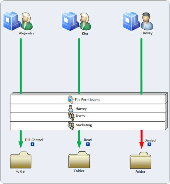
Group Policy scope is the list of all Group Policy objects that may be applicable to the user or computer because of their object’s location within Active Directory. Security Filtering determines if the respective user or computer has the proper permissions to apply the Group Policy object. A user or computer must have the Read and Apply Group Policy permissions for the Group Policy service to consider the Group Policy object applicable to the user.

The Group Policy services iterates through the entire list of Group Policy objects determining if the user or computer has the proper permissions to the GPO. If the user or computer has the permissions to apply the GPO, then the Group Policy service moves that GPO into a filtered list of GPOs. It continues to filter each Group Policy object based on permissions until it reaches the end of the list. The filtered list of Group Policy objects contains all GPOs within scope of the user or computer and are applicable to the user or computer based on permissions.

01-gp

WMI Filtering

WMI filtering is the final phase of determining the scope of Group Policy objects that apply to a user or computer.

Windows Management Instrumentation (WMI) is the Microsoft implementation of Web-Based Enterprise Management (WBEM). WMI uses the Common Information Model (CIM) industry standard to represent systems, applications, networks, devices, and other managed components.

Group Policy provides more filters to control the scope of applicable Group Policy objects. WMI enables you to create queries to interrogate specific features of the computer, operating system, and other managed components. In the form of queries, you create criteria that behave like logical expressions– where the result equates to true or false. You associated, or link these criteria to a Group Policy object. If the criteria evaluates to true, the Group Policy object remains applicable to the user and is kept in the filtered list. If the criteria evaluates to false, the Group Policy service removes the Group Policy object from the filtered list.

Once WMI filtering completes, the Group Policy service has a list of filter Group Policy objects. This final list represents all applicable Group Policy objects for the user or computer. Internally, Security and WMI filtering occur in one cycle.

02-gp

Processing Order

Group Policy has a specific order in which it applies Group Policy objects. Understanding the order in which Group Policy objects apply is important because Group Policy uses the order of application to resolve conflicting policy settings among different Group Policy objects linked to different locations within Active Directory.

Local, Site, Domain, and OU

The Group Policy service applies the Local Group Policy first, then Group Policy objects from the Site, followed by Group Policy objects from the domain, and Group Policy objects from organization units. If the targeted user or computer to receive Group Policy settings, then the Group Policy service applies Group Policy objects from OUs furthest in lineage from the user to closest in lineage to the user. Consider the filtered list of applicable Group Policy objects.

DC=corp,DC=contoso,DC=com OU=RandD,DC=corp,DC=contoso,DC=com
OU=Research,OU=RandD,DC=corp,DC=contoso,DC=com
OU=Managers,OU=Research,OU=RandD,DC=corp,DC=contoso,DC=com

02-gp

Notice the order of Group Policy objects has changed from the first list. This reordering of Group Policy occurs during the Security and WMI filter processing. The Group Policy service builds the first list of GPOs by finding the user or computer object and then collecting all linked GPOs as it walks up the directory tree. The GPOs are listed backwards from the order they apply because as the Group Policy service adds the newly discovered link location to the bottom of the list. This explains why the domain location is at the bottom of the list.

However, when filtering the list for security and WMI filters, the Group Policy service starts at the top of the list, which is the OU closest in lineage to the user or computer object. The service builds a new list (the filtered list) by placing the GPOs that pass through the filter into the filtered list. The service inverts the order of the original list, making the domain location at the top of the list. The location closest to the user is at the bottom of the list —the order Group Policy applies GPOs to users and computers.

Conflict Resolution

Each Group Policy object contains the same number of potential policy settings. Therefore, it is possible to have the same policy setting defined in multiple Group Policy objects. Conflicts occurs when the same policy setting is configured in multiple Group Policy objects. Like two cars competing for the same space on the road—one wins and the other loses. Group Policy handles conflicts by using a method known as last-writer-wins. Last-writer-wins resolves conflicts by declaring the prevailing setting as the setting that Group Policy writes last. Therefore, the Group Policy object containing the conflicting policy setting that applies last is the setting that wins over all other settings.

03-gp

The Processing Order section of this document describes that Group Policy objects apply in Local, Site, Domain, and Organizational Unit order. Based on this processing hierarchy:

  • Policy settings in Group Policy objects linked to the Active Directory site resolve policy setting conflicts between the Local Group Policy object and Group Policy objects linked to the Active Directory site.
  • Policy settings in GPOs linked to the domain resolve policy setting conflicts between Group Policy objects linked to the Active Directory site and GPOs linked to the Active Directory domain.
  • Policy settings in GPOs linked to an organizational unit resolve policy setting conflicts between Group Policy objects linked to the Active Directory domain and GPOs linked to an organizational Unit.
  • Policy settings in GPOs linked to a child organizational unit resolve policy settings conflicts between Group Policy objects linked to the child organizational unit and GPOs linked to the parent organizational unit.

Conflict Resolution among GPOs linked at the same Location

Group Policy enables you to link multiple Group Policy objects at each site, domain, and organization unit locations in the directory. Until now, conflict resolution only identified resolutions between conflicting policy settings linked at two different locations in Active Directory. What about conflicting policy settings in Group Policy objects that are linked at the same location?

Group Policy continues to use the last-writer-wins method for resolving policy setting conflicts among Group Policy objects linked as the same location in Active Directory. Understanding how the Group Policy Management Console (GPMC) links Group Policy objects to locations in Active Directory explains the processing order of Group Policy objects link at the same location in Active Directory.

GPLink Attribute

The locations that support Group Policy linking, Active Directory sites, domains, and organizational units, do so because each of these objects have a GPLink attribute. The GPLink attribute is a single-valued attribute that accepts a value of a string data type. While the Active Directory Schema enforces the single-valued nature of the GPLink attribute, Group Policy uses the attribute as a multivalued attribute. The GPMC writes the value of the GPLink attribute using the following format.

[distinguishedNameOfGroupPolicyContainer;linkOPtions][…][…]

The distingushedNameOfGroupPolicyContainer token represents the distinguished name of the Group Policy Container. A Group Policy object is a single logical object composed of two components of information. The component of information stored on the file system is the Group Policy template. The remaining component, the Group Policy Container is an object in Active Directory object that lives in the domain partition of Active Directory. As previously covered, the distinguished name of a directory object provides the object’s name and location in the directory.

The linkOptions token is an integer value that defines the link options associated with the Group Policy object. Currently, you can enable or disable linked of Group Policy objects. Also, you can configure the link as enforced. The linkOptions value is a bit value where combining values varies the configurations.

Enabled  0x0
Disabled 0x1
Enforced 0x2

Disabling the link of a Group Policy objects prevents the Group Policy service from including that GPO in the list of GPOs within scope of the targeted user or computer. The distinguishedNameOfGroupPolicyContainer and the linkOptions token are enclosed in square brackets ( [ ] ) and separated by a semicolon (;). This represents a singly linked Group Policy object. Linking another Group Policy object to the location inserts a new distingushedNameOfGroupPolicyContainer and linkOptions combination before the existing combination; it does not add the new combination to the end. The linking pattern continues to insert newly linked GPOs at the beginning of the value; by moving existing values to the right.

The Group Policy service reads this long string as a list of values from left to right. The first GPO link entry in the value is the first to apply at this location. The next entry in the value applies afterwards. The process continues until the last GPO in the value applies.

Group Policy inherently assigns each GPO precedence based on the order it reads the list—left to right. Therefore, the first GPO in the value has the lowest precedence in the list of linked Group Policy objects. The next GPO in the value has a higher precedence than the previous GPO because it applies its policy settings after the previous GPO; by winning any policy setting conflicts between the two GPOs. Each GPO that follows has a higher precedence than the Group Policy object before it in the link order. The last GPO in the value has the highest precedence because it is the last Group Policy object the Group Policy service applies.

The best way to understand this is to think of the long string as a list of GPOs. Take the first GPO (the left most GPO) in the value and place it the list. Take the next links GPO listed and place on top of the list (causing all others to move down in the list by one). Continue this process until the last GPO is on top of the list. This final GPO linked entries list is in precedence order, which means the list is processed from the bottom to the top.

05-gp

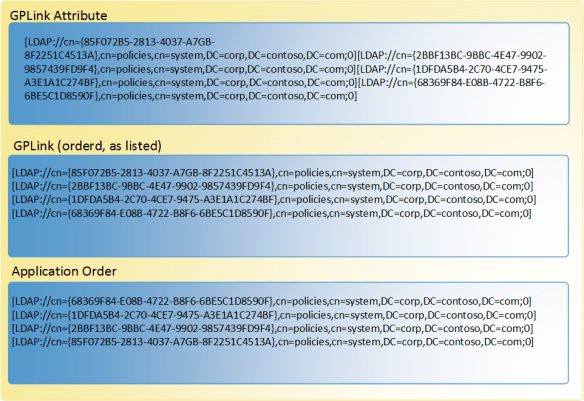
When viewed in a list in precedence order, it’s easy to discover that GPOs higher in the list have more precedence than GPOs lower in the list. As a result, GPOs lower in the list lose policy setting conflicts and GPOs higher in the list win policy setting conflicts.

Link Options

As previously stated, a Group Policy linked as options of enabled, disabled, and enforced. The enabled and disabled options are intuitive to understand. When an enabled link is considered in the scope of Group Policy for the targeted user or computer. A disabled linked behaves as if the Group Policy object was never linked.

Enforced

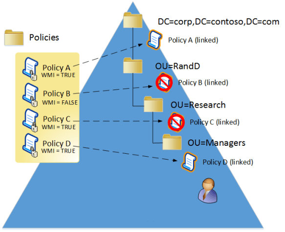
The Enforced link option is the exception to all rules. The Enforced option ensures the settings from the linked GPO always win conflicts regardless of any other Group Policy object that contains policy settings that may conflict with those of the linked GPO. The GPMC visually represents an enforced Group Policy link by adding a padlock to the existing linked policy icon. Group Policy settings from an enforced link always apply, even if the organizational unit has block policy inheritance enabled

Block Policy Inheritance

The last item about Group Policy processing order is Block Policy Inheritance, or simply known as Block Inheritance in the Group Policy Management Console. Each domain and organizational unit in Active Directory object contains a GPOptions attribute. This setting enables you to block Group Policy settings linked higher in the processing order from applying to users and computers that are typically in containers lower in the processing order.

For example, policy settings linked to the domain apply to computers and users within the entire domain, regardless of their parent organizational unit. However, you can use GPMC to block inheritance on the domain or an organizational unit to prevent normal Group Policy setting from applying to users and computers within that container. Blocking policy inheritance on the domain prevents Group Policy settings from GPOs linked to the Active Directory site from applying to the domain. Blocking policy inheritance on organizational units prevents normal Group Policy settings from GPOs linked to sites and domains from applying to the organizational units.

Block policy inheritance does not prevent Group Policy settings from enforced linked Group Policy objects from applying to users and computers. Group Policy settings from enforced links apply regardless of the block policy inheritance status on domain and organizational unit objects.

That wraps up the basics of how the Group Policy engine processes information.

–Mike Stephens


How Windows Server 2012 Eases the Pain of Kerberos Constrained Delegation, Part 2

This article was originally published for Windows IT Pro Magazine, on March 19, 2013.

In How Windows Server 2012 Eases the Pain of Kerberos Constrained Delegation, Part 1, I provided an introduction to resource-based Kerberos constrained delegation, included in Windows Server 2012. I also described the targeted scenarios for which resource-based Kerberos constrained delegation is designed, and provided a brief overview of the technology. Now, in part 2, I want to expand on how resource-based Kerberos constrained delegation works by providing more technical depth as well as a message flow walk through.

Diving into the Technical Depths

Constrained delegation lets you limit the back-end services for which a front-end service can request tickets on behalf of another user. To understand this behavior, it’s best to analyze authentication flow as two separate events: the client authenticating to the front-end service, and the front-end service authenticating to the back-end service.

Client to front-end authentication

Authentication from the Kerberos client to the front-end server doesn’t change when you use resource-based constrained delegation. The Kerberos client requests a service ticket from its local Key Distribution Center (KDC) for the target service principal name (SPN).

If the target service resides in the same domain, the KDC issues a service ticket and session key to the Kerberos client in a TGS-REP message. If the target service resides outside the current domain, the KDC issues a Ticket Granting Ticket (TGT) referral ticket using the inter-realm session key of the trust in a TGS-REP. The Kerberos client chases the referral as it normally does when authenticating to a resource outside of its domain (across a trust).

Front-end to back-end authentication

Authentication from the front end (Service-for-User—S4U—client) to the back end is different when using resource-based constrained delegation. Resource-based constrained delegation requires that the computer running the front-end service use Server 2012 because services running on versions of Windows earlier than Windows 8and Server 2012 don’t support resource-based constrained delegation; earlier versions of Windows don’t chase referrals from the Service-for-User-to-Proxy (S4U2Proxy) TGS-REQ across the domain boundary.

During front-end to back-end authentication, the front-end service asks a KDC for a service ticket on behalf of another user. This exchange uses the Kerberos extension S4U2Proxy (aka constrained delegation). The Kerberos client successfully presents a service ticket to the front-end service. The front-end service impersonates the identity presented in the service ticket and attempts to authenticate to the back-end service by way of SPN. This authentication attempt results in the front-end service creating an S4U2Proxy TGS-REQ to the KDC in the front-end server’s domain. This request includes the target SPN, which resides in another domain, and the service ticket used to authenticate to the front-end service. The TGS-REP returned depends on the answering KDC.

Front-End KDC Behavior

Constrained delegation, at the micro level, involves many decisions and exchanges of information, beginning with the client contacting the front-end KDC.

KDC earlier than Server 2012

A KDC earlier than Server 2012 receiving an S4U2Proxy TGS-REQ for a target SPN outside of its domain returns the Kerberos error KDC_ERR_BADOPTION (13) in a TGS-REP to the front-end service. This response results from an inability of a KDC earlier than Server 2012 to provide a TGT referral for an S4U2Proxy TGT_REQ for a target SPN residing outside its own domain. Constrained delegation prior to Server 2012 wasn’t supported across domain and forest trusts.

Windows Server 2012 KDC

A Server 2012 KDC receiving the S4U2Proxy TGS-REQ determines whether the target SPN resides in its domain. In this scenario, the target SPN resides in another domain. Therefore, the Server 2012 KDC—aware that it supports resource-based constrained delegation—provides a referral TGT to the front-end service in a TGS-REP.

Front-End Service TGS-REP Behavior

The front-end service receives a TGS-REP from the KDC. The next action the front-end service performs depends on the KDC response from the S4U2Proxy TGS-REP.

TGS-REP from KDC earlier than Server 2012

The front-end service receives a TGS-REP in response to the S4U2Proxy TGS-REQ. The response from the KDC is a Kerberos ERROR – KDC_ERR_BADOPTION (13). The front-end service runs on a Server 2012 member server. Server 2012 is a cross-domain constrained delegation–aware Kerberos client; therefore, when the front-end service receives an S4U2Proxy TGS-REP with KDC_ERR_BADOPTION (13), it knows that it might have contacted a KDC that doesn’t support constrained delegation across domains. In response, the Server 2012 member server running the front-end service attempts to locate a Server 2012 domain controller (DC). After locating a Server 2012 DC, the member server running the front-end service sends the same S4U2Proxy TGS-REQ to the Server 2012 DC.

TGS-REP from Server 2012 KDC

The front-end service receives a TGS-REP in response to the S4U2Proxy TGS-REQ. The response from the KDC is a TGT referral to the domain that’s responsible for providing authentication for the target SPN. Server 2012 is a cross-domain constrained delegation–aware Kerberos client. The member server running the front-end service chases the referral to the domain listed in the TGT referral. (Important: When traversing trusts using resource-based constrained delegation, the computer must authenticate to traverse the trust. Therefore, it is expected for the computer to perform a TGS-REQ for a TGT in each domain as well as the first S4U2Proxy TGS-REQ performed by the front-end service.) The TGS-REQ referral process continues until it locates a Server 2012 DC in the domain that hosts the targeted SPN.

Back-End KDC Behavior

The back-end KDC receives an S4U2Proxy TGS-REQ from the front-end service. The TGS-REQ includes an evidentiary ticket, which is the service ticket from the initial authentication to the front-end service as well as the inter-realm referral TGT received from an earlier exchange with a KDC.

The KDC first determines whether the target SPN resides in its domain. If it doesn’t, the KDC creates a referral TGS-REP, as previously described. Alternatively, the target SPN might exist in the current domain. In this case, the KDC can provide a service ticket for the targeted service and can respond directly rather than with a referral to another domain. The KDC then reads the msDS-AllowedToActOnBehalfOfOtherIdentity attribute on the security principal registered for the targeted back-end SPN. If the attribute is empty, the Server 2012 DC will use traditional constrained delegation logic (msDS-AllowedToDelegateTo [A2D2]). If the msDS-AllowedToActOnBehalfOfOtherIdentity has a value, the KDC impersonates the security principal under which the front-end service runs and performs an access check using the security descriptor stored in the msDS-AllowedToActOnBehalfOfOtherIdentity attribute.

An access check failure causes the KDC to use traditional constrained delegation logic (A2D2) to determine whether constrained delegation is allowed. A successful access check means the back-end service allows the front-end service to request tickets on behalf of other security principals that are used for authentication to the back-end service. The KDC builds a service ticket for the back-end service using the client name from the evidentiary ticket and returns the service ticket and session key for the front-end service to use to authenticate to the back-end service as the user.

KDC Behavior With and Without Traditional Constrained Delegation

If the back-end server is configured using traditional constrained delegation (msDS-AllowedToDelegateTo—A2D2), which must reside in the same domain, then a Server 2012 KDC or a KDC running an earlier version of Windows can be used for authentication.

Behavior for non-Server 2012 KDCs

KDCs running earlier versions of Windows behave the same with traditional constrained delegation. If A2D2 isn’t configured, and the back-end service resides in the current domain, the KDC returns KDC_ERR_BADOPTION with a sub status of STATUS_NOT_FOUND. If A2D2 isn’t configured, and the back-end service resides in another domain, the KDC returns KDC_ERR_BADOPTION with a sub status of STATUS_NOT_FOUND.

If A2D2 is configured, and the back-end service is not a value in the attribute, and the back-end service resides in the current domain, the KDC returns KDC_ERR_BADOPTION with a sub status of STATUS_NOT_FOUND. If the back-end service resides in another domain, the KDC returns KRB-ERR-POLICY with a sub status of STATUS_CROSSREALM_DELEGATION_FAILURE.

Behavior for Server 2012 KDCs

If A2D2 isn’t configured, and the back-end service resides in another domain, the Server 2012 KDC returns a referral TGT. If A2D2 isn’t configured, and the back-end service resides in the current domain, and resource-based constrained delegation isn’t configured on the principal object, the Server 2012 KDC returns KDC_ERR_BADOPTION with a sub status of STATUS_NOT_FOUND.

If A2D2 is configured, and the back-end SPN isn’t a value within the attribute, the back-end service resides in the current domain, and resource-based constrained delegation isn’t configured on the principal object, the Server 2012 KDC returns KDC_ERR_BADOPTION with a sub status of STATUS_NOT_FOUND. If the back-end SPN resides in another domain, the Server 2012 KDC returns a referral TGT.

Message Flow Walk through

Now that all the academic explanation is out of the way, here’s a walk through of the message flow to help you visualize how all of this works together. Don’t worry if you don’t understand all of it the first time! It’s a lot to take in, and the changes are a shift in thinking from how delegation used to work to how it can work in Server 2012. When teaching this material, I explain to engineers that if they think it’s too simple, then they’re catching on! The management of it is simple, but the inner workings require a little more thought before they make sense.

To reduce the number of visible steps to those included in the resource-based constrained delegation message exchange, successful client-to-front-end authentication is assumed in Figure 1.

p2-AuthenticationFlow

Figure 1.

  1. The front-end service sends an S4U2Proxy TGS-REQ to the KDC in root.fabrikam.com, requesting a service ticket for the back-end service on behalf of the user. The TGS-REQ includes the front-end service TGT; a forwardable client service ticket for the front-end service, or an evidentiary ticket; and the KDC option cname-in-addl-tkt. If the KDC in root.fabrikam.com returns KRB-ERR-BADOPTION, the front-end service locates a Server 2012 DC and retries the TGS-REQ.
  2. The KDC in root.fabrikam.com determines that the back-end service doesn’t reside in root.fabrikam.com and returns a referral TGT for corp.contoso.com to the front-end service on behalf of the user. The cname field in the ticket uses the name of the front-end service, and the crealm field uses the name of the front-end service domain.
  3. The front-end service must authenticate to the back-end domain to chase the referral on behalf of the user. The front-end service sends a TGS-REQ, as itself, to the KDC in the root.fabrikam.com to request a service ticket for the back-end service.
  4. The KDC in root.fabrikam.com determines that the back-end service isn’t in root.fabrikam.com and returns a TGS-REP that includes a referral TGT to corp.contoso.com.
  5. The front-end service sends a TGS-REQ, for itself, requesting a service ticket for the back-end service.
  6. The KDC in corp.contoso.com sends a TGS-REP that includes a service ticket for the back-end service that is used by the front-end service.
  7. The front-end service locates a Server 2012 DC in corp.contoso.com and sends an S4U2Proxy TGS-REQ to the KDC in corp.contoso.com, requesting a service ticket for the back-end service on behalf of the user present in the evidentiary ticket. The request includes a front-end service referral TGT, additional tickets (S4U referral TGT), and the KDC option cname-in-addl-tkt.
  8. The KDC in corp.contoso.com retrieves account information from AD using SamIGetUserLogonInformation, impersonates the front-end service, and performs an access check using the security descriptor in the msDS-AllowedToActOnBehalfOfOtherIdentity attribute. If the access check fails, the KDC returns KRB-ERR-BADOPTION; otherwise, the KDC returns a service ticket in a TGS-REP)
  9. The front-end service presents the service ticket requested on behalf of the user to the back-end service by sending an AP-REQ.
  10. The back-end service returns an AP-REP if mutual authentication is required.

Protocol Transition (S4U2Self)

The protocol transition extension to Kerberos doesn’t require a Server 2012 DC. Therefore, Windows 8 and Server 2012 S4U clients don’t attempt to locate a Server 2012 DC to service these requests.

Front-end servers need to locate Server 2012 DCs when the initial S4U2Proxy TGS-REQ returns a KRB-ERR-BADOPTION or KRB-ERR-POLICY. To accomplish this, the S4U client uses the public directory service API DsGetDCName, which makes an RPC call to a DC. The specific call includes the DS_DIRECTORY_SERVICE_8_REQUIRED flag, which indicates the API need only return Server 2012 DCs.

This wraps up resource-based constrained delegation, and now you can see how it eases the administrative pains of constrained delegation. Server 2012 simplifies its configuration. It removes the appearance of registering duplicate SPNs on multiple front-end computers, returns the point management to the resource owner rather than the owner of the front-end service and the domain administrator. Also, with resource-based constrained delegation, you can now use constrained delegation across trusted domains and trusted forests—a feature that has been a huge request from customers for a long time.

–Mike Stephens

Understand and Troubleshoot Dynamic Access Control in Windows Server 2012

I finished the update to the very popular guide to Dynamic Access Control. Everything you wanted to know about Dynamic Access Control, but cannot find anywhere else.

  • Technical concepts to help you successfully install, configure, and manage this feature.
  • Technical concepts to help you successfully install, configure, and manage this feature.
  • Relevant architecture of this feature, with dependencies, and technical implementation.
  • Primary troubleshooting tools and methods for this feature.

You can download it directly from Microsoft here or, you can slurp it from the blog directly (in case Microsoft moves or deletes items from their download center).

UTG-DynamicAccessControl-Feb2013

— Mike Stephens

How Windows Server 2012 Eases the Pain of Kerberos Constrained Delegation, Part 1

Originally published for Windows IT Pro Magazine, February 22, 2013

Let’s talk authentication—specifically, Kerberos constrained delegation. But first, if you’re new to Kerberos or need a quick refresher, I would suggest that you read the Ask the Directory Services Team blog posts “Kerberos for the Busy Admin” and “Understanding Kerberos Double Hop” to get up to speed on the terminology and concepts contained throughout this article. Part 1 of this article describes the benefits of using Kerberos constrained delegation with Windows Server 2012 over earlier versions of Windows Server. Part 2 will provide a technical walk through of how Kerberos constrained delegation works in Server 2012.

What Is Constrained Delegation?

Constrained delegation lets you limit the back-end services for which a front-end service can request tickets on behalf of another user. A common example of constrained delegation is the web-browser-to-IIS-to-SQL-Server scenario. In this scenario, a user navigates to a web-based reports server hosted on Microsoft IIS, which retrieves data using an authenticated connection to a Microsoft SQL Server system. The IIS server needs to authenticate to the SQL Server system on behalf of the user. Through Kerberos delegation, the IIS server (i.e., the front-end service) can request a service ticket for any service (i.e., back-end service)—not just SQL Server—on behalf of the user. This means that the IIS server can essentially authenticate on behalf of the user to SQL Server, a file share, or a web service. Using constrained delegation, you can limit the IIS server (the front end) so that it can authenticate the user only to SQL Server (the back end) and no other service or application.

Kerberos constrained delegation has been a part of the OS since Windows Server 2003. It requires you to configure an allow list of service principal names (SPNs) on user or computer objects in Active Directory (AD). You add the list of SPNs that represent the back-end services to which a front-end service is allowed to request tickets on behalf of the user to the ms-DS-Allowed-To-Delegate-To attribute of the principal under which the application or service on the front-end server runs. In the previous example, the front-end service is IIS and the back-end service is SQL Server. To constrain the delegation for IIS, you would add SPNs for the SQL Server instances running on the SQL Server system to the ms-DS-Allowed-To-Delegate-To attribute on the IIS computer account in AD—or the user account running the IIS application pool. This model constrains the front-end service to only request service tickets that are listed in the ms-DS-Allowed-To-Delegate-To attribute. The downside of this delegation model is that it relies heavily on SPNs.

Service Principal Names

SPNs are difficult to manage. Although they’re simple in concept, SPNs can cause a significant amount of frustration, stemming from unique constraints associated with using them.  Kerberos uses SPNs to identify the security principal responsible for running an application or service. This enables the Key Distribution Center (KDC) to encrypt tickets and keys with the correct hash so that the security principal (running the service or application) can decrypt the service ticket upon receiving the AP_REQ. This design requires that SPNs registered on security principals be unique for the AD forest. An SPN registered on multiple security principals will cause authentication to fail.

Constrained delegation appears to contradict the basic rule of registering a duplicate SPN; however, this is only in appearance. The KDC doesn’t look at the ms-DS-Allowed-To-Delegate-To attribute when trying to map an SPN to a security principal. Therefore, the unique SPN requirement is limited only to values in the servicePrincipalName attribute. To constrain the delegation of a service or application, you must list the service’s SPNs on the security principal that runs the application on the front-end server.  Managing the number of SPNs, knowing when and where to register them, and avoiding duplicates is cumbersome. This makes constrained delegation difficult to implement, maintain, and troubleshoot

Point of Delegation

Constrained delegation is a model that controls delegation on the front-end server. Most delegation models manage the point of delegation closest to the resource (i.e., on the back end). Implementing delegation on the front end removes control from the resource administrator and places it on the administrator of the front-end server (and application). This model prevents the resource administrator from managing access to the resource. The current model requires domain administrative privileges to modify the ms-DS-Allowed-To-Delegate-To attribute, thus adding more administrative overhead to the management of constrained delegation.

Scope of Delegation

Scope of delegation refers to the limit to which the delegation extends from the front-end server to the back-end server. The current constrained delegation model scope is limited to the domain, meaning that the security principal under which the application or service runs can forward constrained delegated tickets only to an application or service running under a security principal in the same domain. You can’t use constrained delegation across domain or forest trusts.

What Server 2012 Brings

Windows Server 2012 introduces a new kind of Kerberos constrained delegation that addresses many of the shortcomings that exist with the previous constrained delegation model. The new implementation of constrained delegation removes the dependencies on SPNs for delegation configuration, removes the need for domain administrative privileges, enables the resource administrator to own the delegation experience, and increases the scope of delegation.

Constrained delegation in Server 2012 introduces the concept of controlling delegation of service tickets using a security descriptor rather than an allow list of SPNs. This change simplifies delegation by enabling the resource to determine which security principals are allowed to request tickets on behalf of another user.

Figure 1 shows a sample scenario. A server in Domain A runs an IIS application. The security principal under which the IIS application’s AppPool runs has the SPNs registered for the front-end service or application (HTTP/app1.contoso.com). These SPNs allow the user to authenticate to the front-end server using normal Kerberos authentication.

00-figure-01

Figure 1.

The application retrieves data from a back-end server in Domain B running SQL Server. The security principal running the SQL Server service has the SPNs registered for SQL Server and SQL Server instances. Again, this configuration is normal to enable Kerberos authentication. The KDC in the domain hosting the security principal running SQL Server receives a Service-for-User-to-Proxy (S4U2Proxy) Ticket Granting Service (TGS) request from the IIS server on behalf of another user. The KDC reads the security descriptor stored in the msDS-AllowedToActOnBehalfOfOtherIdentity attribute on the security principal running the SQL Server service and performs an access check using the identity under which the IIS Application Pool runs. A successful access check allows the authentication process to continue, whereas an unsuccessful access check fails the authentication attempt.

Resource-based constrained delegation functions correctly regardless of domain functional level and number of domain controllers (DCs) running a version of Windows Server prior to Server 2012, provided you have at least one Server 2012 DC in the same domain as the front-end server and one Server 2012 DC in the domain hosting the back-end server. When the domain is a hybrid domain (both Server 2012 DCs and DCs running an earlier version of Windows Server), then Windows 8 and Windows 2012 computers ensure they use a Server 2012 DC to use resource-based constrained delegation by deliberately locating a Server 2012 DC.

Requirements

The new implementation of Kerberos constrained delegation has the following requirements:

  •  Server 2012 KDCs must reside in the front-end account domain
  •  Server 2012 KDCs must reside in the back-end account domain
  •  The front-end server must run Server 2012

Server 2012 KDCs are required for this feature because these are the only KDCs that know how to return referred S4U2Proxy requests and use the new msDS-AllowedToActOnBehalfOfOtherIdentity attribute on the service account. The front-end server requires Server 2012 because the version of Kerberos on these servers understands that it must chase S4U2Proxy referrals to trusted domains and forests.

Management

You manage Server 2012 Kerberos constrained delegation using Windows PowerShell. Use the following Windows PowerShell cmdlets to manage constrained delegation. Typically, you’ll want to use the Get-ADUser, Get-ADComputer, or Get-ADServiceAccount of the principal running the front-end service and pass that principal object as the argument value to the -PrincipalsAllowedToDelegateToAccount argument.

Set-ADComputer computerName -PrincipalsAllowedToDelegateToAccount principal1, principal2, ...
Set-ADUser userName -PrincipalsAllowedToDelegateToAccount principal1, principal2, ...
Set-ADServiceAccount serviceAccountName -PrincipalsAllowedToDelegateToAccount principal1, principal2, ...
Get-ADComputer computerName -Property PrincipalsAllowedToDelegateToAccount
Get-ADUser userName -Property PrincipalsAllowedToDelegateToAccount
Get-ADServiceAccount serviceName -Property PrincipalsAllowedToDelegateToAccount

Stay Tuned for More

This article identifies the challenges IT pros face when implementing Kerberos constrained delegation. Server 2012 provides a compelling answer to these problems by introducing resource-based Kerberos constrained delegation. In Part 2 of this series, I’ll provide a more in-depth analysis of how resource-based constrained delegation works and look at the flow of authentication that’s exchanged between computers running Server 2012.

–Mike Stephens

Windows Server 2012 Shell game

Here’s the scenario, you just downloaded the RTM ISO for Windows Server 2012 using your handy, dandy, “wondermus” Microsoft TechNet subscription. Using Hyper-V, you create a new virtual machine, mount the ISO and breeze through the setup screen until you are mesmerized by the Newton’s cradle-like experience of the circular progress indicator00-shellGameClick…click…click…click– installation complete; the computer reboots.

You provide Windows Server with a new administrator password. Bam: done! Windows Server 2012 presents the credential provider screen and you logon using the newly created administrator account, and then…

Holy Shell, Batman! I don’t have a desktop!01-shellGame
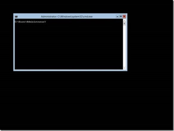
The previously described scenario is not hypothetical– many have experienced it when they installed the pre-release versions of Windows Server 2012. And it is likely to resurface as we move past Windows Server 2012 general availability on September 4. If you are new to Windows Server 2012, then you’re likely one of those people staring at a command prompt window on your fresh installation. The reason you are staring at command prompt is that Windows Server 2012’s installation defaults to Server Core and in your haste to try out our latest bits, you breezed right past the option to change it.

This may be old news for some of you, but it is likely that one or more of your colleagues is going to perform the very actions that I describe here. This is actually a fortunate circumstance as it enables me to introduce a new Windows Server 2012 feature.02-shellGameThere were two server installation types prior to Windows Server 2012: full and core. Core servers provide a low attack surface by removing the Windows Shell and Internet Explorer completely. However, it presented quite a challenge for many Windows administrators as Windows PowerShell and command line utilities were the only methods used to manage the servers and its roles locally (you could use most management consoles remotely).

Those same two server installation types return in Windows Server 2012; however, we have added a third installation type: Minimal Server Interface. Minimal Server Interface enables most local graphical user interface management tasks without requiring you to install the server’s user interface or Internet Explorer. Minimal Server Interface is a full installation of Windows that excludes:

  • Internet Explorer
  • The Desktop
  • Windows Explorer
  • Windows 8-style application support
  • Multimedia support
  • Desktop Experience

Minimal Server Interface gives Windows administrators – who are not comfortable using Windows PowerShell as their only option – the benefit a reduced attack surface and reboot requirement (i.e., on Patch Tuesday); yet GUI management while the ramp on their Windows PowerShell skills.03-shellGame“Okay, Minimal Server Interface seems cool Mike, but I’m stuck at the command prompt and I want graphical tools. Now what?” If you were running an earlier version of Windows Server, my answer would be reinstall. However, you’re running Windows Server 2012; therefore, my answer is “Install the Server Graphical Shell or Install Minimal Server Interface.”

Windows Server 2012 enables you to change the shell installation option after you’ve completed the installation. This solves the problem if you are staring at a command prompt. However, it also solves the problem if you want to keep your attack surface low, but simply are a Windows PowerShell guru in waiting. You can choose Minimal Server Interface ,or you can decided to add the Server Graphical Interface for a specific task, and then remove it when you have completed that management task (understand, however, that switching between the Windows Shell requires you to restart the server).

Another scenario solved by the ability to add the Server Graphical Shell is that not all server-based applications work correctly on server core, or you cannot management them on server core. Windows Server 2012 enables you to try the application on Minimal Server Interface and if that does not work, and then you can change the server installation to include the Graphical Shell, which is the equivalent of the Server GUI installation option during the setup (the one you breezed by during the initial setup).

Removing the Server Graphical Shell and Graphical Management Tools and Infrastructure

Removing the Server shell from a GUI installation of Windows is amazingly easy. Start Server Manager, click Manage, and click Remove Roles and Features. Select the target server and then click Features. Expand User Interfaces and Infrastructure.

To reduce a Windows Server 2012 GUI installation to a Minimal Server Interface installation, clear the Server Graphical Shell checkbox and complete the wizard. To reduce a Windows Server GUI installation to a Server Core installation, clear the Server Graphical Shell and Graphical Management Tools and Infrastructure check boxes and complete the wizard.04-shellGame
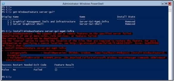
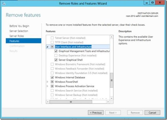
Alternatively, you can perform these same actions using the Server Manager module for Windows PowerShell, and it is probably a good idea to learn how to do this. I’ll give you two reasons why: It’s wicked fast to install and remove features and roles using Windows PowerShell and you need to learn it in order to add the Server Shell on a Windows Core or Minimal Server Interface installation.

Use the following command to view a list of the Server GUI components05-shellGame

Get-WindowsFeature server-gui*

Give your attention to the Name column. You use this value with the Remove-WindowsFeature and Install-WindowsFeature PowerShell cmdlets.

To remove the server graphical shell, which reduces the GUI server installation to a Minimal Server Interface installation, run:

Remove-WindowsFeature Server-Gui-Shell

To remove the Graphical Management Tools and Infrastructure, which further reduces a Minimal Server Interface installation to a Server Core installation.

Remove-WindowsFeature Server-Gui-Mgmt-Infra

To remove the Graphical Management Tools and Infrastructure and the Server Graphical Shell, run:

Remove-WindowsFeature Server-Gui-Shell,Server-Gui-Mgmt-Infra

Adding Server Graphical Shell and Graphical Management Tools and Infrastructure

Adding Server Shell components to a Windows Server 2012 Core installation is a tad more involved than removing them. The first thing to understand with a Server Core installation is the actual binaries for Server Shell do not reside on the computers. This is how a Server Core installation achieves a smaller footprint. You can determine if the binaries are present by using the Get-WindowsFeature Windows PowerShell cmdlets and viewing the Install State column. The Removed value indicates the binaries that represent the feature do not reside on the hard drive. Therefore, you need to add the binaries to the installation before you can install them. Another indicator that the binaries do not exist in the installation is the error you receive when you try to install a feature that is removed. The Install-WindowsFeature cmdlet will proceed along as if it is working and then spend a lot of time around 63-68 percent before returning an error stating that it could not add the feature.06-shellGame

To stage Server Shell features to a Windows Core Installation

You need to get our your handy, dandy media (or ISO) to stage the binaries into the installation. Windows installation files are stored in WIM files that are located in the \sources folder of your media. There are two .WIM files on the media. The WIM you want to use for this process is INSTALL.WIM.07-shellGame
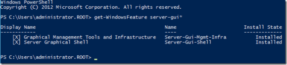
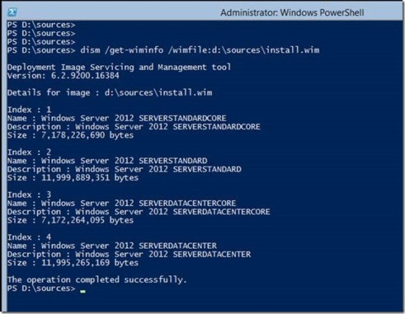
You use DISM.EXE to display the installation images and their indexes that are included in the WIM file. There are four images in the INSTALL.WIM file. Images with the index of 1 and 3 are Server Core installation images for Standard and Datacenter, respectively. Images with the indexes 2 and 4 are GUI installation of Standards and Datacenter, respectively. Two of these images contain the GUI binaries and two do not. To stage these binaries to the current installation, you need to use indexes 2 and 4 because these images contain the Server GUI binaries. An attempt to stage the binaries using indexes 1 or 3 will fail.

You still use the Install-WindowsFeature cmdlets to stage the binaries to the computer; however, we are going to use the -source argument to inform Install-WindowsFeature the image and index it should use to stage the Server Shell binaries. To do this, we use a special path syntax that indicates the binaries reside in a WIM file. The Windows PowerShell command should look like

Install-WindowsFeature server-gui-mgmt-infra,server-gui-shell -source:wim:d:\sources\install.wim:4

Pay particular attention to the path supplied to the -source argument. You need to prefix the path to your installation media’s install.wim file with the keyword wim: You need to suffix the path with a :4, which represents the image index to use for the installation. You must always use an index of 2 or 4 to install the Server Shell components. The command should exhibit the same behavior as the previous one and proceeds up to about 68 percent, at which point it will stay at 68 percent for a quite a bit, (if it is working). Typically, if there is a problem with the syntax or the command it will error within two minutes of spinning at 68 percent. This process stages all the graphical user interface binaries that were not installed during the initial setup; so, give it a bit of time. When the command completes successfully, it should instruct you to restart the server. You can do this using Windows PowerShell by typing the Restart-Computer cmdlets.08-shellGameGive the next reboot more time. It is actually updating the current Windows installation, making all the other components aware the GUI is available. The server should reboot and inform you that it is configuring Windows features and is likely to spend some time at 15 percent. Be patient and give it time to complete. Windows should reach about 30 percent and then will restart.09-shellGame
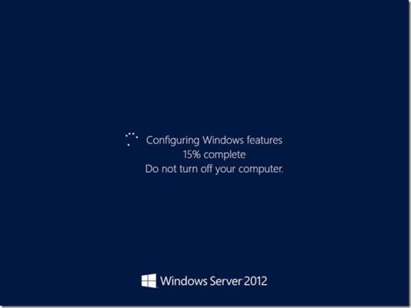
It should return to the Configuring Windows feature screen with the progress around 45 to 50 percent (these are estimates). The process should continue until 100 percent and then should show you the Press Ctrl+Alt+Delete to sign in screen.10-shellGame

Done

That’s it. Consider yourself informed. The next time one of your colleagues gazes at their accidental Windows Server 2012 Server Core installation with that deer-in-the-headlights look, you can whip our your mad Windows PowerShell skills and turn that Server Core installation into a Minimal Server Interface or Server GUI installation in no time.

— Mike Stephens

MaxTokenSize and Windows 8 and Windows Server 2012

I want to share with you some of the excellent enhancements we accomplished in Windows 8 and Windows Server 2012 around MaxTokenSize. Let’s review MaxTokenSize and its symptoms before we jump in to wonderful world of Windows 8 (say that three times fast).

Wonderful World of Windows 8

What is MaxTokenSize

Kerberos is the default and preferred authentication protocol since the release of Windows 2000 Server. Over the last few years, Microsoft has made some significant investments in provided extensions to the protocol. One of those extensions to Kerberos is the Privilege Attribute Certificate or PAC (defined in Windows Server Protocol specification MS-PAC).

Microsoft created the PAC to encapsulate authorization related information in a manner consistent with RFC4120. The authorization information included in the PAC includes security identifiers, user profile information such as Full name, home directory, and bad password count. Security identifiers (SIDs) included in the PAC represent the user’s current SID and any instances of SID history and security group memberships to the extent of current domain groups, resource domain groups, and universal groups.

Kerberos uses a buffer to store authorization information and reports this size to applications using Kerberos for authentication. MaxTokenSize is the size of buffer used to store authorization information. This buffer size is important because some protocols such as RPC and HTTP use it when they allocate memory for authentication. If the authorization data for a user attempting to authenticate is larger than the MaxTokenSize, then the authentication fails for that connection using that protocol. This explains why authentication failures resulted when authenticating to IIS but not when authenticating to folder shared on a file server. The default buffer size for Kerberos in Windows 7 and Windows Server 2008R2 is 12k.

Windows 8 and Windows Server 2012

Let’s face the facts of today’s IT environment… authentication and authorization is not getting easier; it’s becoming more complex. In the world of single sign-on and user claims, the amount of authorization data is increasing. Increasing authorization data in an infrastructure that has already had its experiences with authentication failures because a user was a member of too many groups justifies some concern for the future. Fortunately, Windows 8 and Windows Server 2012 have features to help us take proactive measures to avoid the problem.

Default MaxTokenSize

Windows 8 and Windows Server 2012 benefit from an increased MaxTokenSize of 48k. Therefore, when HTTP relies on the MaxTokenSize value as the value used for memory allocation; it will allocate 48k of memory for the authentication buffer, which hold a substantially more authorization information than in previous versions of Windows where the default MaxTokenSize was only 12k.

Group Policy settings

Windows 8 and Windows Server 2012 introduce two new computer-based policy settings that help combat against large service tickets, which is the cause of the MaxTokenSize dilemma. The first of these policy settings is not exactly new– it has been in Windows for years, but only as a registry value. Use the policy setting Set maximum Kerberos SSPI context token buffer size to change the MaxTokenSize using group policy. Looking closely at this policy setting in the Group Policy Management Editor, you’ll notice the icon for this setting is slightly different from the others around it.

00-maxToken
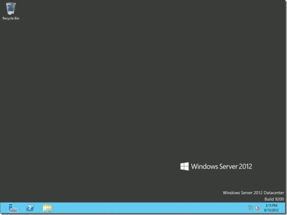
This difference is attributed to registry location the policy setting modifies when enabled or disabled. This registry setting is the actual MaxTokenSize registry key and value name that has been used in earlier versions of Windows

HKEY_LOCAL_MACHINE\SYSTEM\CurrentControlSet\Control\Lsa\Kerberos\Parameters\MaxTokenSize

Therefore, you can use this computer-based policy setting to manage Windows 8, Windows Server 2012, and earlier versions of Windows. The catch here is that this registry location is not a managed policy location. Managed policy locations are removed and reapplied during policy refreshes to avoid persistent settings in the registry after the settings in a Group Policy object become out of scope. That behavior does not occur with this key, as the setting applied by this policy setting is not removed during application. Therefore, the policy setting persists even if the Group Policy object providing the setting falls out of scope.

The second policy setting is very cool and answers the question that customers always asked when they encounter a problem with MaxTokenSize: “How big is the token?” You might be one of those people that went on the crusade of a lifetime using TOKENSZ.EXE and spent countless hours trying to determine the optimal MaxTokenSize for your environment. Those days are gone.

A new KDC policy settings Warning events for large Kerberos tickets provides you with a way to monitor the size of Kerberos tickets issued by KDCs. When you enable this policy setting, you then must configure a ticket threshold size. The KDC uses the ticket threshold size to determine if it should write a warning event to the system event log. If the KDC issues a ticket that exceeds the ticket threshold size, then it writes a warning. This policy setting, when enabled, defaults to the 12k, which is the default MaxTokenSize of previous version of Windows.

01-maxToken
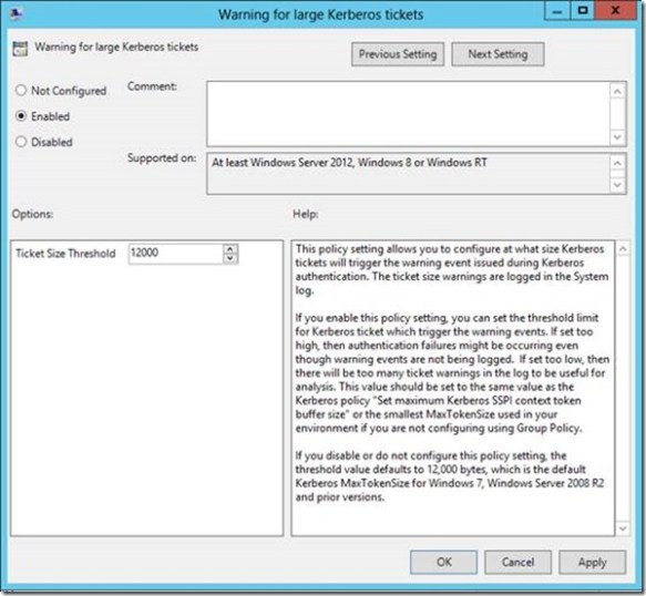
Ideally, if you use this policy setting, then you’d likely want to set the ticket threshold value to approximately 1k less than your current MaxTokenSize. You want it lower than your current MaxTokenSize (unless you are using 12k, that is the minimum value) so you can use the warning events as a proactive measure to avoid an authentication failure due to an incorrectly sized buffer. Setting the threshold too low will just train you to ignore the Event 31 warnings because they’ll become noise in the event log. Setting it too high and you’re likely to be blindsided with authentication failures rather than warning events.

02-maxToken
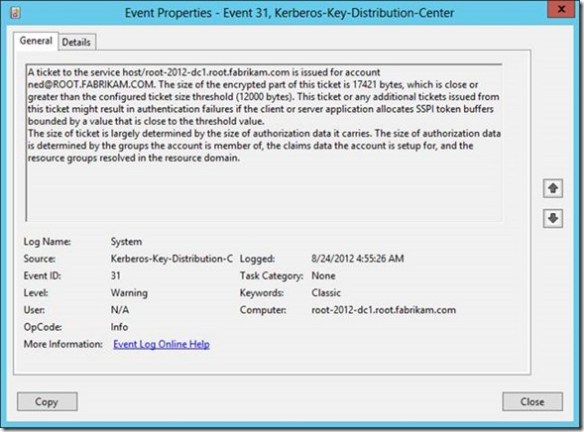
Earlier I said that this policy setting solves your problems with fumbling with TOKENSZ and other utilities to determine MaxTokenSize– here’s how. If you examine the details of the Kerberos-Key-Distribution-Center Warning event ID 31, you’ll notice that it gives you all the information you need to determine the optimal MaxTokenSize in your environment. In the following example, the user Ned is a member of over 1000 groups (he’s very popular and a big deal on the Internet). When I attempt to log on Ned using the RUNAS command, I generated an Event ID 31. The event description provides you with the service principal name, the user principal name, the size of the ticket requested and the size of the threshold. This enables you to aggregate all the event 31s and identify the maximum ticket size requested. Armed with this information, you can set the optimal MaxTokenSize for your environment.

03-maxToken

KDC Resource SID Compression

Kerberos authentication inserts security identifiers (SIDs) of the security principal, SID history, all the groups to which the user is a member including universal groups and groups from the resource domain. Security principals with too many group memberships greatly affect the size of the authentication data. Sometimes the authentication data is larger than the allocated size reported by Kerberos to applications. This can causes authentication failure in some applications. SIDs from the resource domain share the same domain portion of the SID, these SIDs can be compressed by only providing the resource domain SID once for all SIDs in the resource domain.

Windows Server 2012 KDCs help reduce the size of the PAC by taking advantage of resource SID compression. By default, a Windows Server 2012 KDC will always compress resource SIDs. To compress resource SIDs, the KDC stores SID of the resource domain to which the target resource is a member.  Then, it inserts only the RID portion of each resource SID into the ResourceGroupIds portion of the authentication data.

Resource SID Compression reduces the size of each stored instance of a resource SID because the domain SID is stored once rather than with each instance. Without resource SID Compression, the KDC inserts all the SIDs added by the resource domain in the Extra-SID portion of the PAC structure, which is a list of SIDs.  [MS-KILE]

Interoperability

Other Kerberos implementations may not understand resource group compression and therefore are not compatible. In these scenarios, you may need to disable resource group compression to allow the Windows Server 2012 KDC to interoperate with the third-party Kerberos implementation.

Resource SID compression is on by default; however, you can disable it. You disable resource SID compression on a Windows Server 2012 KDC using the DisableResourceGroupsFields registry value under the HKLM\Software\Microsoft\Windows\CurrentVersion\Policies\System\Kdc\Parameters registry key. This registry value has a DWORD registry value type. You completely disable resource SID compression when you set the registry value to 1. The KDC reads this configuration when building a service ticket. With the bit enabled, the KDC does not use resource SID compression when building the service ticket.

Wrap up

There’s the skinny on the Kerberos enhancements included in Windows 8 and Windows Server 2012 that specifically target large service ticket and MaxTokenSize scenarios. To summarize:

  • Increased default MaxTokenSize from 12k to 48k
  • New Group Policy setting to centrally manage MaxTokenSize
  • New Group Policy setting to write warnings to the system event log when a service ticket exceeds a designated threshold
  • New Resource SID compression to reduce the storage size of SIDs from the resource domain

Keep an eye out for more Windows 8 and Kerberos needful

— Mike Stephens

Cluster and Stale Computer Accounts

Today, I want to write about a common administrative task that can lead to disaster: removing stale computer accounts from Active Directory.

Removing stale computer accounts is simply good hygiene– it’s the brushing and flossing of Active Directory. Like tartar, computer accounts have the tendency to build up until they become a problem (difficult to identify and remove, and can lead to lengthy backup times).

Oops… my bad

Many environments separate administrative roles. The Active Directory administrator is not the Cluster Administrator. Each role holder performs their duties in a somewhat isolated manner– the Cluster admins do their thing and the AD admins do theirs. The AD admin cares about removing stale computer accounts. The cluster admin does not… until the AD admin accidentally deletes a computer account associated with a functioning Failover Cluster because it looks like a stale account.

Unexpected deletion of Cluster Name Object (CNO) or Virtual computer Object (VCO) is one of the top issues worked by our engineers that support Clustering and High-Availability. Everyone does their job and boom– Clustered Servers stop working because CNOs or the VCOs are missing. What to do?

What’s wrong here

I’ll paraphrase an article posted on the Clustering and High-Availability TechNet blog that solves this scenario. Typically, domain admins key on two different attributes to determine if a computer account is stale: pwdlastSet and LastLogonTimeStamp. Domains that are not configured to a Window Server 2003 Domain Functional Level use the pwdLastAttribute. However, domains configured to a Windows Server 2003 Domain Functional Level or later should use the lastLogonTimeStamp attribute. What you may not know is that a Failover Cluster (CNO and VCO) does not update the lastLogonTimeStamp the same way as a real computer.

Cluster updates the lastLogonTimeStamp when it brings a clustered network name resource online. Once online, it caches the authentication token. Therefore, a clustered network named resource working in production for months will never update the lastLogonTimeStamp. This appears as a stale computer account to the AD administrator. Being a good citizen, the AD administrator deletes the stale computer account that has not logged on in months. Oops.

The Solution

There are few things that you can do to avoid this situation.

  • Use the servicePrincipalName attribute in addition to the lastLogonTimeStamp attribute when determining stale computer accounts. If any variation of MSClusterVirtualServer appears in this attribute, then leave the computer account alone and consult with the cluster administrator.
  • Encourage the Cluster administrator to use -CleanupAD to delete the computer accounts they are not using after they destroy a cluster.
  • If you are using Windows Server 2008 R2, then consider implementing the Active Directory Recycle Bin. The concept is identical to the recycle bin for the file system, but for AD objects. The following ASKDS blogs can help you evaluate if AD Recycle Bin is a good option for your environment.

— Mike Stephens